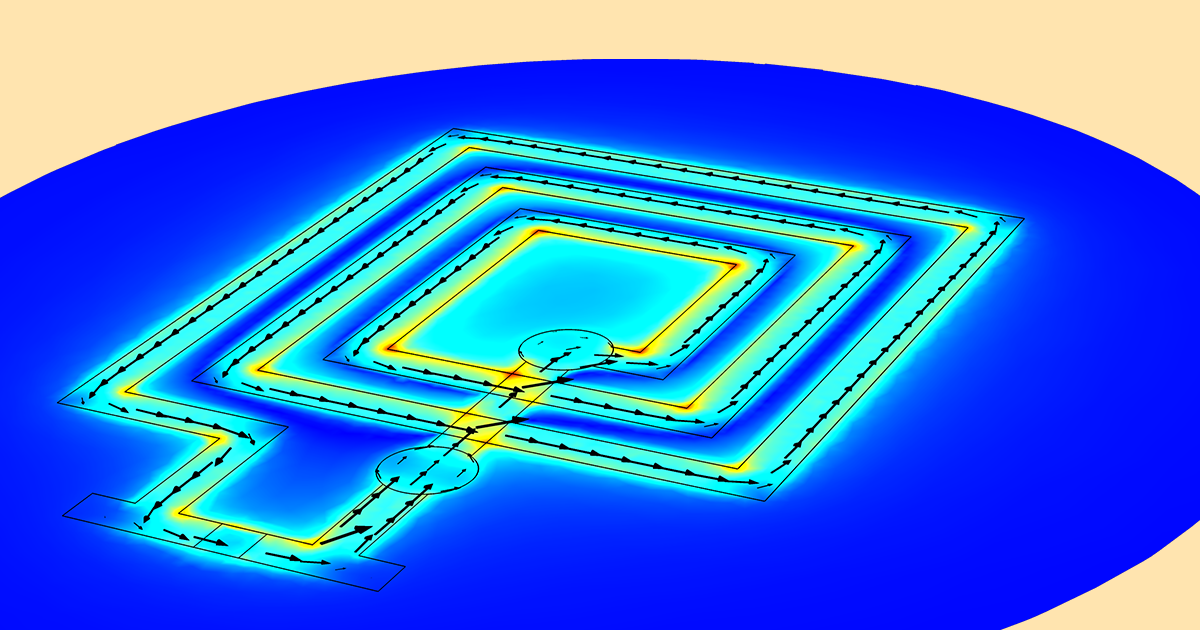
A printed circuit board (PCB) coil is a crucial part of several electrical gadgets. PCB coils are used in power supply and RF circuits due to their ability to store energy and produce magnetic fields. A PCB coil may appear challenging, but with the correct equipment and supplies, you can create one in no time. This post will show you How to Make PCB Coil from scratch.
Acquire Resources
Get your supplies in order before you get started. Copper wire, a PCB board, and a soldering iron are the components required to construct a PCB coil. Additional equipment consists of wire cutters, pliers, and a ruler. A multimeter is also helpful in checking the coil’s resistance and inductance.
Establishing Coil Requirements
Identifying the coil’s requirements is the next stage. The number of turns, wire size, and coil diameter are all listed. Application-specific requirements may be established with the use of software or internet calculators. When the parameters have been settled, it is time to choose the copper wire gauge and diameter.
Getting the PCB Board Ready
Getting the PCB board ready is the next stage. Before soldering, the board must be cleaned with alcohol to eliminate any dirt or oils. Once the board has been well-cleaned, a design may be sketched to show where the coil will be installed. The holes needed to secure the coil to the circuit board should be included in the design.
Wind the coil
The coil must now be wound. A cylindrical item of the correct diameter, such as a pencil or a dowel, should be wrapped in copper wire that has been cut to the right length. To produce a stable and robust magnetic field, it is essential that the number of turns remains constant and that the wire is twisted securely. After winding the coil, the ends of the wire should be shortened so that they are just long enough to connect to the PCB.
The coil must be soldered
Securing the coil to the printed circuit board (PCB) is the next step. Using a soldering iron, connect the coil’s wire ends in place by threading them through the corresponding holes in the PCB board. To achieve a solid connection, the solder should be applied uniformly and thoroughly to cover the wire and board. The surplus wire may be cut away once the coil has been soldered into position.
Coil Testing
The PCB coil is finished and ready for testing. The coil’s resistance and inductance may be checked using a multimeter to ensure they are suitable for the intended function. It may be necessary to rewind or fine-tune the coil to get it to the desired parameters.
Conclusion
Making a PCB coil is straightforward, with the correct equipment and supplies. The process begins with selecting the appropriate coil parameters and continues through constructing the PCB board, winding the coil, soldering it to the board, and finally testing the ring. According to these guidelines, a high-quality PCB coil may be made suitable for the intended use.
